
The production of LED modules involves a meticulous process combining advanced technology and exquisite craftsmanship.
From preparing the PCB board to assembling indoor and outdoor modules, quality and functionality are ensured at every step.
The following is a detailed breakdown of the production process:
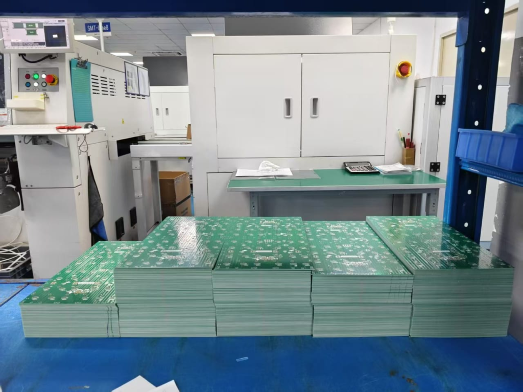
(1) Labeling the PCB
Production begins with affixing identification labels to the PCB (Printed Circuit Board).
These labels serve as unique identifiers for quality control and tracking throughout the production cycle.
The labels also include key details such as batch number, production date, and specifications, making inventory management and identification of any defects easier.
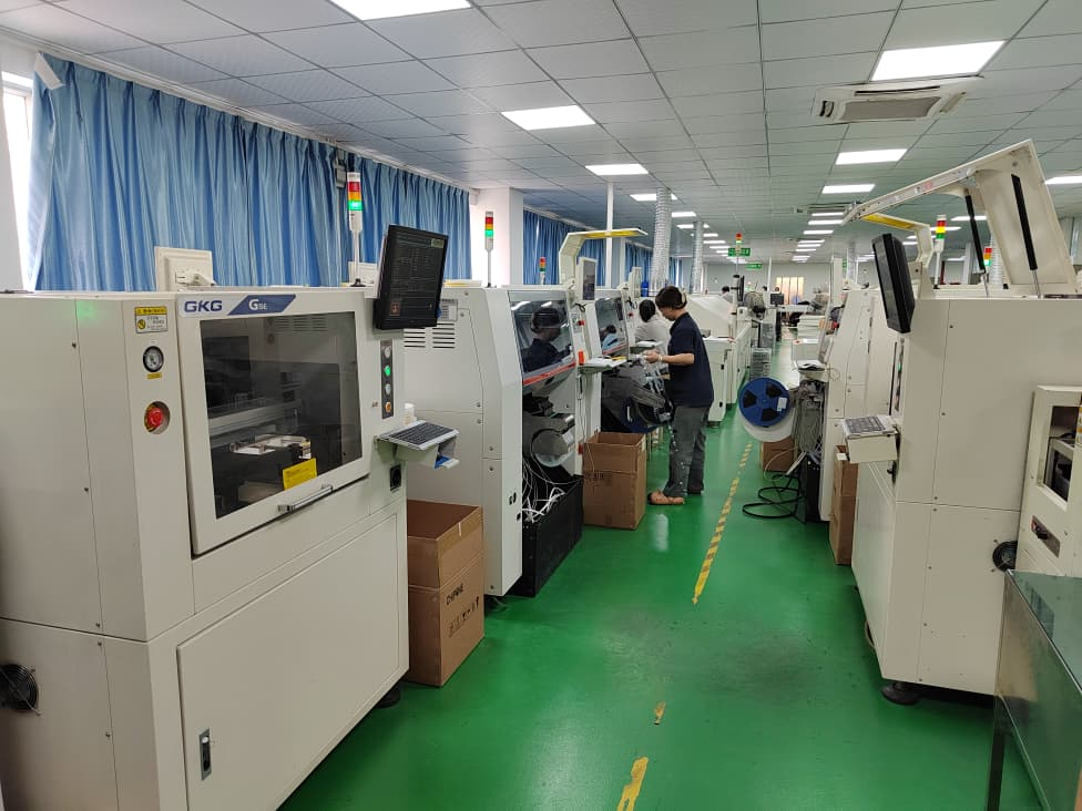
(2) Applying Solder Paste to the IC Surface
Solder paste is a mixture of fine solder particles and flux. It is precisely applied to the IC (Integrated Circuit) area of the PCB.
This is done using an automated stencil machine to ensure uniform coverage and accuracy.
The solder paste acts as a temporary adhesive, holding the components in place and establishing electrical connections before soldering.
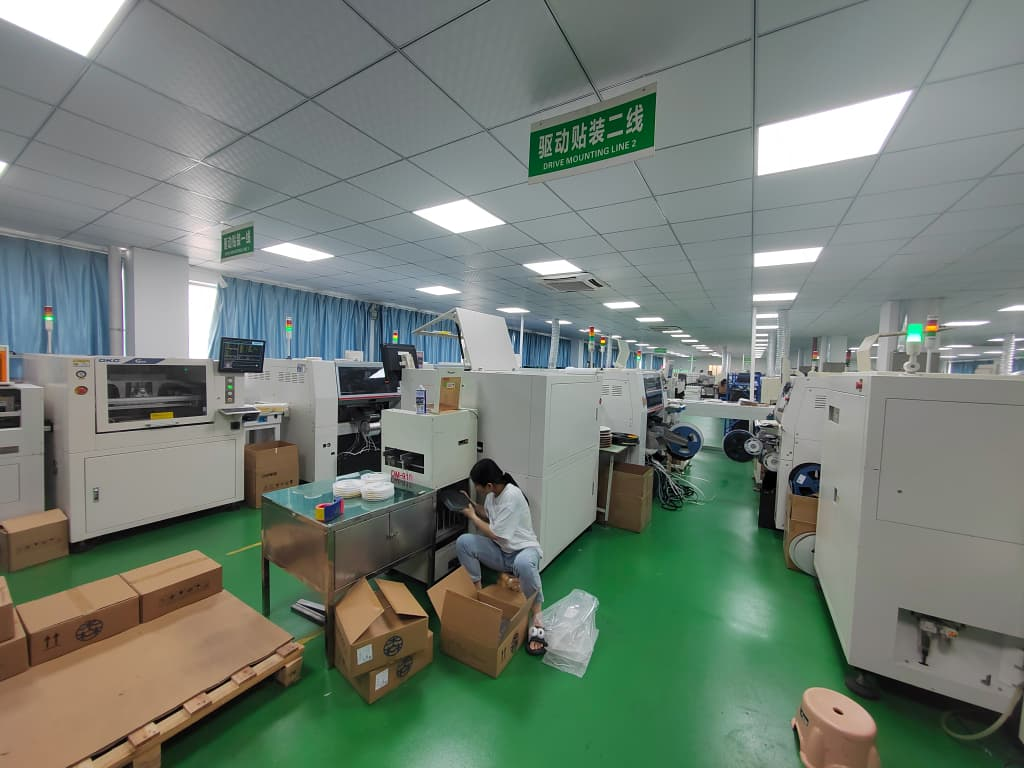
(3) Connecting Resistors, ICs, Capacitors, and Power Interfaces
After applying the solder paste, key electronic components such as resistors, ICs, capacitors, and power interfaces are mounted on the PCB.
This process is typically performed using surface mount technology (SMT) machines. SMT machines can place components with high precision and speed.
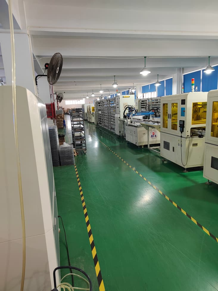
These components are crucial for controlling the power supply, processing, and overall functionality of the LED module. (4) High temperature reflow soldering
The PCB and its mounted components pass through a reflow oven where they undergo a carefully controlled heating process.
The solder paste melts and solidifies, forming a strong mechanical and electrical connection.
At this stage, the temperature needs to be closely monitored to prevent damage to sensitive components. This is also a necessary measure to ensure the long-term reliability of the LED module.
(5) Inspection and sorting of LED module
After reflow soldering, the modules are visually inspected and tested.
Automated optical inspection (AOI) systems are often used to inspect for defects such as component misalignment, welding issues, or damaged parts.
Defective mods will be put on hold for rework, while approved mods will be organized for next steps.
(6) Applying Solder Paste to the LED Surface
This process now focuses on the LED surface on the PCB.
A new layer of solder paste is applied using a stencil printer. This paste will hold the LED in place before soldering.
The accuracy of this step is crucial. Uneven application will lead to poor connections and inconsistent brightness in the LED display module.
(7) Installing the LEDs
The LEDs are the core component of the LED display module.
Advanced placement machines can precisely mount the LEDs onto the PCB. Precise positioning ensures consistent pixel alignment.
The quality of the LED chips determines the brightness, color accuracy, and viewing angle of the finished LED module.
(8) High temperature reflow soldering of LED
The PCB with the LEDs mounted goes through a second round of reflow soldering.
This process holds the LED beads in place, ensuring they are securely attached and electrically connected.
A stable welding process is crucial as it affects the performance and durability of the LED screen module.
(9) Heat dissipation and LED module testing
After welding, the LED module is cooled to stabilize its structure.
It is then rigorously tested to ensure it meets the performance standards of high-quality LED panel display modules. Testing includes power-on test, brightness check and color calibration.
Faulty modules will be marked for rework or rejected to maintain product quality.